On-field in-situ balancing of industrial blower or impeller is a very convenient and precise way to reduce machine vibrations. In-situ balancing refers to field balancing of rotating machine in its place of assembly without requiring to dismantle the machine structure. Additionally, the results obtained are of the entire machine structure and helps in analysis of vibration related problems other than unbalance. This saves considerable efforts, time and costs.
Our proprietary automatic 2-round field balancing method uses external stroboscope to indicate the actual point of unbalance in first round without requiring external tachometer input or manually tuned speed input. Read more about how it automatically derives machine speed from vibration unbalance signal on our blog Single plane field balancing
In this discussion we will clarify how to use stroboscope for field balancing in different conditions. This discussion applies to all types of industrial centrifugal and axial fans including blowers, ID fans, FD fans, impellers, cooling tower fans which are either direct driven or belt driven. Drive or mounting arrangements can be any of the below mentioned types:
-
Direct mounted or integrally directly connected to the motor
-
Overhung with one bearing in bracket
-
Overhung with two bearings on base on the same side
-
Center mounted with two bearings, one of each side
In almost all scenarios with the exception of cooling tower fan, the industrial blower or impeller will be enclosed with a small inspection window opening. For this discussion, we will be considering only single plane field balancing of industrial blower or impeller to simplify the concept. Below assumptions have been taken into consideration:
-
Industrial blower or impeller is considered to be single plane since the distance between its two plates is very less.
-
Addition or removal of weight is done on the back plate
-
In case of overhung mounting, accelerometer is mounted on bearing A as shown in figure 2
-
If the vibrations at one bearing reduces and at other increases during the procedure, then you must consider performing dual plane balancing and check unbalance location on both planes. As long as overall vibrations at both bearings are reduced, single plane balancing is sufficient.


Field balancing equipment
Equipment required for field balancing is termed as field balancing equipment or portable dynamic balancing machine or portable vibration analyzer and balancer or a combination of above terms which all mean the same. We will be using metro B6012 .
Accelerometer mounting
Vibration sensor or accelerometer will be the zero reference while using Automatic 2-round balancing, i.e. point of unbalance will be indicated with respect to accelerometer. It will be mounted in horizontal direction on the nearest bearing housing using a strong magnet. In case the blower or impeller is directly driven, accelerometer will be mounted on motor's bearing housing, not on the motor housing. The size and/or weight capacity of industrial blower or impeller which can be balanced using portable balancing equipment is not a relevant measure since the industrial blower or impeller is driven by its own motor and the portable balancer does not bear it's load. Accelerometer should be mounted as close to the industrial blower or impeller as possible. Note that accelerometer should only be mounted on stationary object directly in contact with the rotating structure under maintenance like bearing housing and not on the casing or enclosure of the industrial blower or impeller.
Field balancing setup
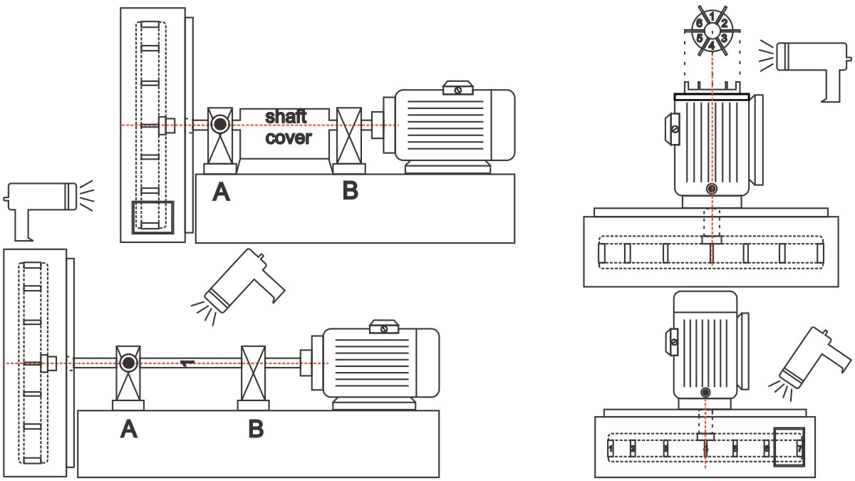
Using external stroboscope for field balancing requires to mark equidistant characters (numbers, letters, etc.) on the rotating object for visually indicating the point of unbalance. You can read more about it's operation principal in our single plane field balancing blog. When an industrial blower or impeller is rotating, all its connected parts are rotating synchronously with it, like shaft, motor's rotor and motor's back fan. It is not always feasible or convenient to mark equidistant characters on the industrial blower or imepller and observe point of unbalance through the inspection window. In such cases, equidistant markings can be done either on the directly connected shaft (by removing the shaft cover) or on the motor's fan (by removing the back plate).
Total vibration measurement and analysis
It is always a good idea to first measure and analyze vibrations in all 3 directions (horizontal, vertical and axial) on all bearings and confirm the major cause of vibrations to be unbalance and then proceed for field balancing.
Field balancing method
We will be using Automatic 2-round field balancing method described in our blog Single plane field balancing
Location of point of unbalance
Point of unbalance for adding or removing weight (as per your selection in the metro B6012) will be indicated by the character marking, appearing visually steady during stroboscope flashing, in straight line with the horizontally mounted accelerometer. Accelerometer is the zero reference. Read details about it's working in our blog. The concept is simple: observe unbalance location at any easily accessible location which rotates synchronously with the blower or impeller under maintenance. This point can then be extended in a straight line to locate the point on blower or impeller. Unbalance location can be observed in any one of the following ways:
-
On the blower or impeller by marking characters on it from the inspection window as shown in figure 3
-
On the shaft by marking characters as shown in figure 4
-
On the motor fan by marking characters and removing the motor back cover as shown in figure 5


Adding or removing trial weight
Addition or removal of trial weight must always be performed on the industrial fan and not on the shaft even though the marking may be on shaft or motor's back fan. While adding or removing weight through the inspection window, rotate the industrial blower or imepller to bring the observed marking at the inspection window and perform process at this location only. If it is not feasible to add or remove weight at the indicated point of unbalance, either use the nearest feasible location or split the desired weight into two and add or remove on either sides.